加
載
中

Bulgar Eden Enterprise Co., LTD. collaborated with the Department of Civil Engineering at National Yunlin University of Science and Technology (Yuntech) to conduct a research project titled “Vibration Behavior of Stay Cables and Anchorage Stress Analysis,” officially funded by the National Science Council under project code NSC 99-2622-E-224-007-CC3.
A key objective of this collaboration was to carry out fatigue stress testing on BE’s proprietary T15 three-part anchorage wedges, an essential component of the BE Post-Tensioning System. The tests were conducted at Yuntech’s structural engineering lab using the MTS-810 universal testing machine and were designed to simulate various stress amplitudes, upper stress limits, and angular deviations.
All testing followed the technical requirements set forth by Taiwan’s construction guidelines (Section 03231, “Prestressing Tendons and Anchorage”) and the recommendations of the Post-Tensioning Institute (PTI). Results confirmed that the T15 wedges successfully met or exceeded the fatigue performance standards, including the stringent limits of 0.8fPK and Δf=816 kgf/cm² locally, and f=0.45fPK and Δf=228MPa internationally.
The test results demonstrated excellent fatigue resistance under varied and demanding stress conditions, validating the safety and reliability of BE’s anchorage technology in stay cable applications. This successful industry-academia collaboration reinforces Bulgar Eden’s commitment to developing verified, high-performance post-tensioning systems for critical infrastructure projects.
Plan name: Fatigue Life and Parameter Study of Wedge-Type Anchors for Prestressing Tendons
Plan number: NSC 99-2622-E-224 -007 -CC3
Time: June 1, 2010 to May 31, 2011
Host: Associate Professor Chien-Chou Chen
Test Product: T15 3-pieces wedges from BE PT system
Test items: fatigue test with a single strain(fs: upper limit stress)
◈ 1. span force: spanΔf=2300kgf/cm2, upper limit force: f=0.6, 0.65, 0.7, 0.8fs (fig. 1)
◈ 2. upper limit force f=0.8fs, span force Δf=800, 1200, 1680, 2000, 2300kgf/cm2 (fig. 2)
◈ 3. upper limit force f=0.65fs, span force Δf=2300kgf/cm2, deflection=0.3°, 0.6°, 0.9°(fig.3)
◈ 4. upper limit force f=0.65fs, span force Δf=800, 1200, 1680, 2000kgf/cm2, deflection=3.5° (fig.4)
Measurement Place: Construction science building in NYUST
Instruments: MTS-810 Universal Testing Machine (25Tons)
Reference:
1. Taiwanese Construction Guide Line ch. 03231, “PT Strain and Wedges”, test upper limit, f=0.8fPK、span Δf=816 kgf/cm2
2. 2. US Post Tensioning Institute (PTI),Recommendations for stay cable design, testing and installation, upper limit f=0.45fPK, span Δf=228MPa
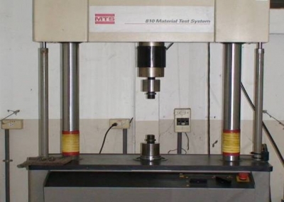
MTS-810 Universal test machine
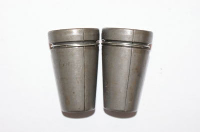
BE-T15 3-pieces wedges
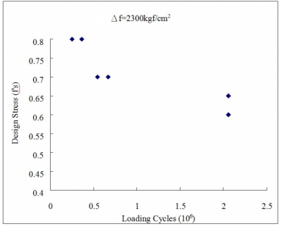
Fig. 1 Upper limit force and loaded fatigue test
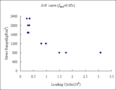
Fig. 2 S-N Curve(upper limit force 0.8f’s)
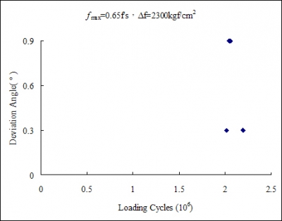
Fig. 3 Deflection and fatigue loaded fatigue test
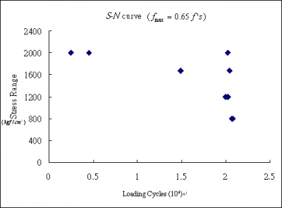
Fit. 4 Deflection 3.5° S-N curve(upper limit force 0.65f’s)